A logic gate is an elementary building block of a digital circuit. Most logic gates have two inputs and one output. At any given moment, every terminal is in one of the two binary conditions low (0) or high (1), represented by different voltage levels.
2.1 BASIC REVISION OF LOGIC GATES
here i put a video that i take from youtube.com which i think its will help you to understand what is logic gate for starting.
https://www.youtube.com/watch?v=Xi18hI1LqAA
Boolean aljebra uses variables and operators to represent logic circuits.The variables and function have only one value, 0 and 1. The complement of a variable is shown by a bar over the letter such as A' or A not.
There are have 6 basic logic circuit, which are AND, OR, NOT, NOR, NAND and XOR.

This table shows the basic logic gate.
PREPARED BY: SITI ROSNIEZA EILISA BINTI JAMAL (B031410230)
BOOLEAN EQUATION FORM
A boolean algebra is the combination of variables and operators.typycally,it has one or more inputs and produces an output in the range of 0 or 1.the complement of a variable is shown by a bar over letter.
sum of product(sop)

product of sums
https://www.youtube.com/watch?v=K1Fxknoo-og
PREPERED BY:NOR FADILA BT MOHD YUNUS,B031410253
SIMPLIFICATION OF BOOLEAN EQUATION.
LAWS OF BOOLEAN ALGEBRA

Laws of Boolean Algebra Example No1
Using the above laws, simplify the following expression: (A + B)(A + C)
| Q = | (A + B)(A + C) | |
| AA + AC + AB + BC | - Distributive law | |
| A + AC + AB + BC | - Identity AND law (A.A = A) | |
| A(1 + C) + AB + BC | – Distributive law | |
| A.1 + AB + BC | - Identity OR law (1 + C = 1) | |
| A(1 + B) + BC | - Distributive law | |
| A.1 + BC | - Identity OR law (1 + B = 1) | |
| Q = | A + BC | - Identity AND law (A.1 = A) |
Then the expression: (A + B)(A + C) can be simplified to A + BC
KARNAUGH MAP.


PREPARED BY : MASTURAH BINTI MOHAMMAD LIZA , B031410271
UNIVERSAL GATE
NAND GATE

The above diagram is of a two input NAND gate. The first part is an AND gate and second part is a dot after it represents a NOT gate. So it is clear that during the operation of NAND gate, the inputs are first going through AND gate and after that the output is reversed and we get the final output. Now we will look at the truth table of NAND gate.
We will consider the truth table of the above NAND gate i.e. a two input gate. The two inputs are A and B.
| A | B | OUT |
|---|---|---|
| 0 | 0 | 1 |
| 1 | 0 | 1 |
| 0 | 1 | 1 |
| 1 | 1 | 0 |
Now we will see how this gate can be used to make other gates.
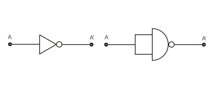
Realization of NOT gate by NAND gate
This is the circuit diagram of a NAND gate used to make work like a NOT gate, the original logic gate diagram of NOT gate is given beside.

The above diagram is of an OR gate made from combinations of NAND gates, arranged in a proper manner. The truth table of an OR gate is also given beside the diagram. Now we will see the design of an AND gate from NAND gates.

The above diagram is of an AND gate made from NAND gate. So we can see that all the three basic gates can be made by only using NAND gates, that’s why this gate is called Universal Gate and it is appropriate.
The above diagram is of an AND gate made from NAND gate. So we can see that all the three basic gates can be made by only using NAND gates, that’s why this gate is called Universal Gate and it is appropriate.
- http://www.electrical4u.com/universal-gate-nand-nor-gate-as-universal-gate/
PREPARED BY SITI NORHAYATI BINTI MASHUDI B031410259
NOR GATE

We have seen how NAND gate can be used to make all the three basic gates by using that alone. Now we will discuss the same in case of NOR gate.

The above diagram is of an OR gate made by only using NOR gates. The output of this gate is exactly similar to that of a single OR gate. As we can see the circuit arrangement of OR gate using NOR gates is similar to that of AND gate using NAND gates.
The above diagram is of an OR gate made by only using NOR gates. The output of this gate is exactly similar to that of a single OR gate. As we can see the circuit arrangement of OR gate using NOR gates is similar to that of AND gate using NAND gates.


NOR gates are so-called "universal gates" that can be combined to form any other kind of logic gate.
A NOR gate is logically an inverted OR gate. By itself has the following truth table:
Truth Table
Input A Input B Output Q
0 0 1
0 1 0
1 0 0
1 1 0
NOR AS XOR
An XOR gate is made by connecting the output of 3 NOR gates (connected as an AND gate) and the output of a NOR gate to the respective inputs of a NOR gate. This expresses the logical fomula (A AND B) NOR (A NOR B). This construction entails a propagation delay three times that of a single NOR gate.
NOR AS XNOR
An XNOR gate can be constructed from four NOR gates implementing the expression "(A NOR N) NOR (B NOR N) where N = A NOR B".This construction has a propagation delay three times that of a single NOR gate, and uses more gates.
- http://www.electrical4u.com/universal-gate-nand-nor-gate-as-universal-gate/
- http://www.instructables.com/id/NOR-as-Universal-Gate/
PREPARED BY : WAN NORAQILAH BINTI A.RAZAK (B031410306)
No comments:
Post a Comment